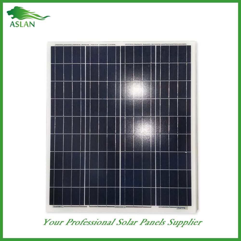
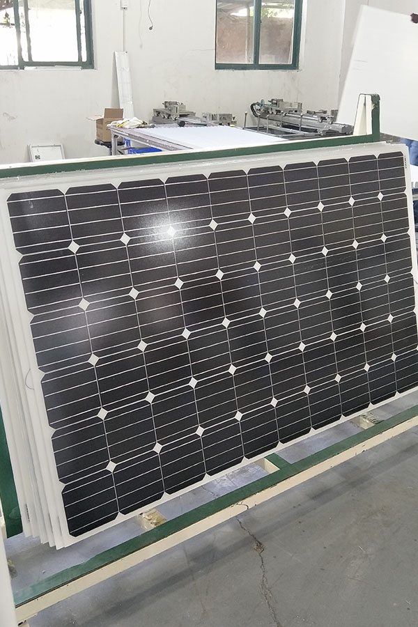
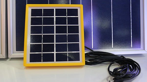
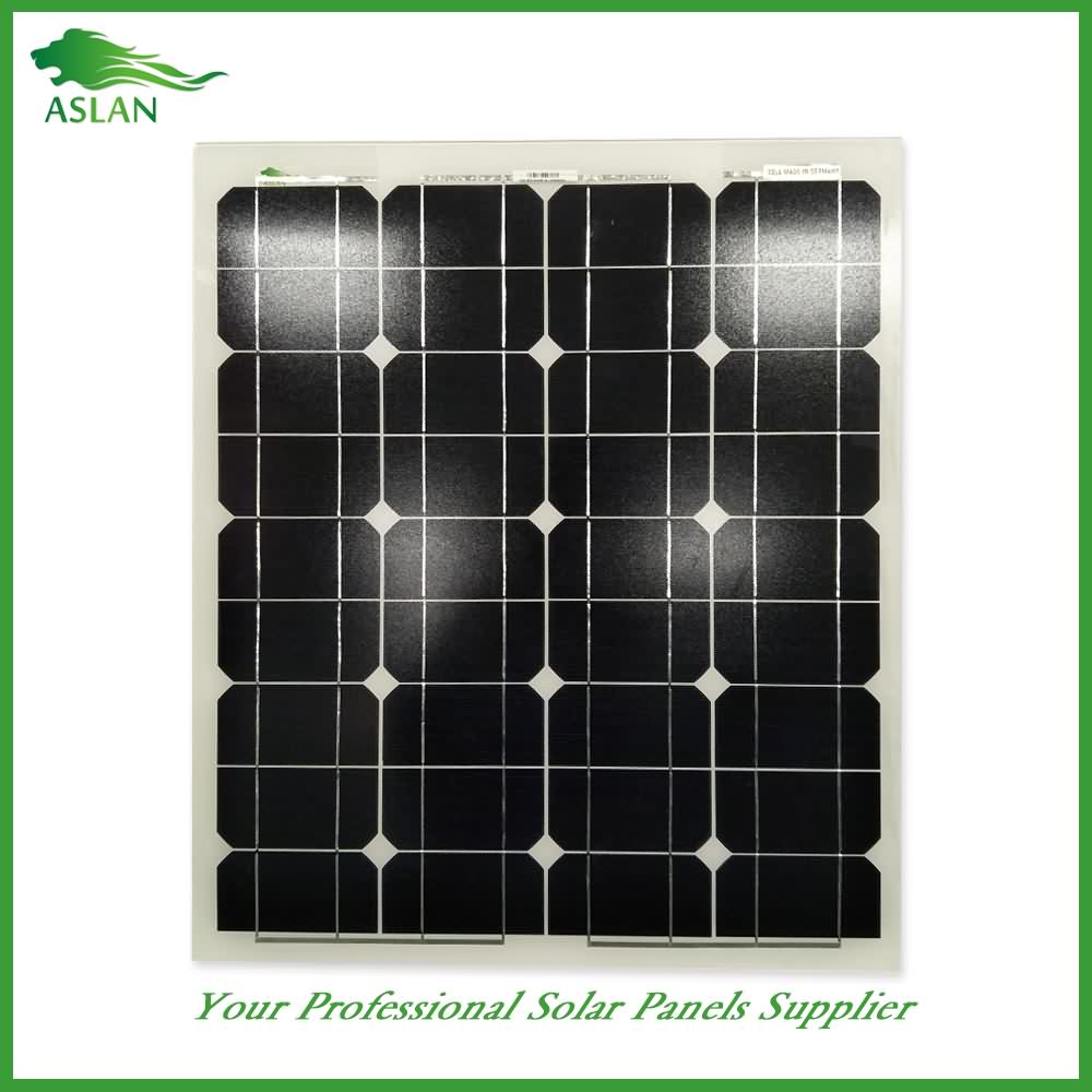
Ordinary Discount Poly-crystalline Solar Panel 40W to Montpellier Factories
Short Description:
We depend on sturdy technical force and continually create sophisticated technologies to meet the demand of Ordinary Discount Poly-crystalline Solar Panel 40W to Montpellier Factories, we are seeking for extensive cooperation with honest customers, achieving a new cause of glory with customers and strategic partners.
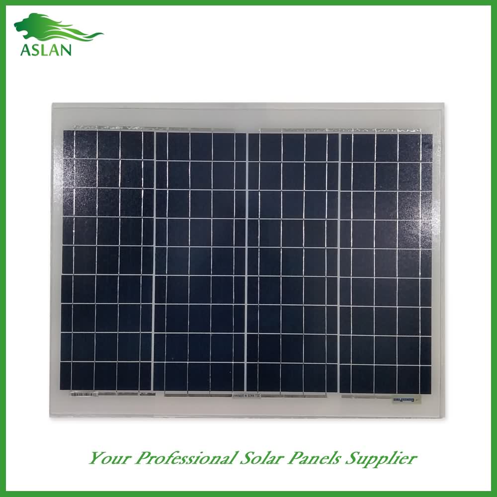
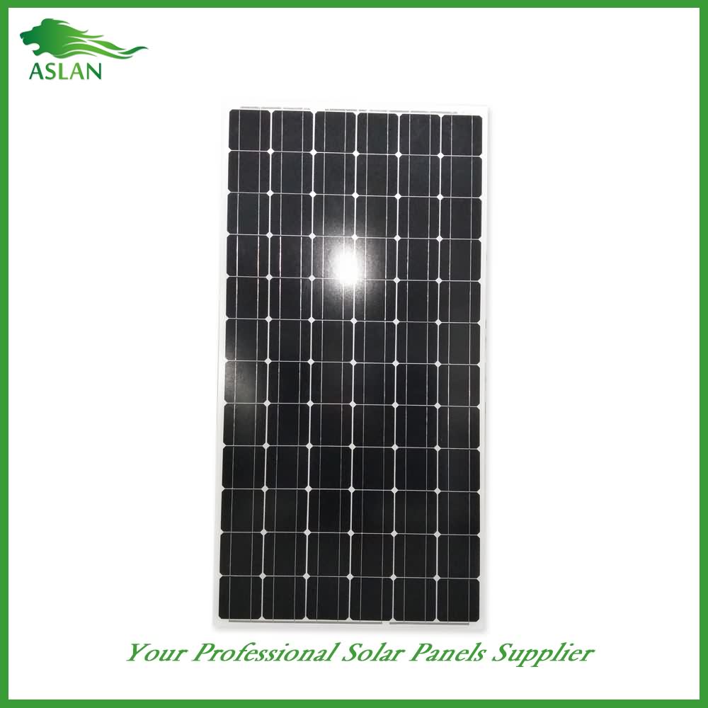
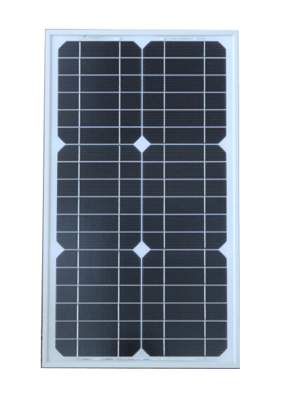
Poly-crystalline Solar Panel 40W
Technical parameter
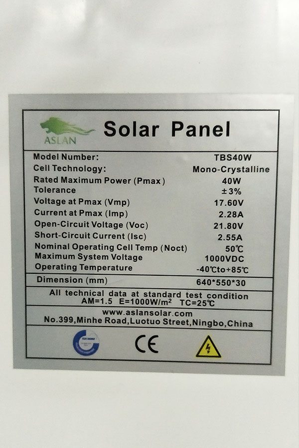
Maximum Power(W) 40W
Optimum Power Voltage(Vmp) 17.35V
Optimum Operating Current(Imp) 2.31A
Open Circuit Voltage(Voc) 21.16V
Short Circuit Current(Isc) 2.53A
Mechanical Characteristics
Cell Type Polycrystalline 156 x 52mm
No of Cell 36 (4x9pcs)
Dimensions 670x420x30mm
Weight 4.0Kg
Front Glass 3.5mm,High Transmission, Low Iron,Tempered Glass
Junction box IP65 Rated
Output Cable TUV 1×4.0mm2/UL12AWG,Length:900mm
Temperature and Coefficients
Operating Temperature(°C): -40°C ~ + 85°C
Maximum System Voltage: 600V(UL)/1000V(IEC) DC
Maximum Rated Current Series: 15A
Temperature Coefficients of Pmax: -0.47%
Temperature Coefficients of Voc: -0.389%
Temperature Coefficients of Isc: 0.057%
Nominal Operationg Cell Temperature (NOCT): 47+/-2°C
Materials of solar panel
1).Solar Cell——Polycrystalline solar cell 156*52mm
2).Front Glass——-3.2mm, high transmission, low iron, tempered glass
3).EVA——-excellent anti-aging EVA
4).TPT——-TPT hot seal made of flame resistance
5).Frame——anodized aluminum profile
6).Junction Box——-IP65 rated, high quality, with diode protection
Superiority: high quality anodized aluminum frame, high efficiency long life, easy installation, strong wind resistance, strong hail resistance.
Features
1. High cell efficiency with quality silicon materials for long term output stability
2. Strictly quality control ensure the stability and reliability, totally 23 QC procedures
3. High transmittance low iron tempered glass with enhanced stiffness and impact resistance
4. Both Poly-crystalline and Mono-crystalline
5. Excellent performance in harsh weather
6. Outstanding electrical performance under high temperature and low irradiance
Quality assurance testing
Thermal cycling test
Thermal shock test
Thermal/Freezing and high humidity cycling test
Electrical isolation test
Hail impact test
Mechanical, wind and twist loading test
Salt mist test
Light and water-exposure test
Moist carbon dioxide/sulphur dioxide
Common issue pertaining to thin film solar modules: how to make the cells inside a large panel, transparent conductive oxides (TCO) for thin film solar modules.
Week 9, Lecture 17, Part 3
Nov 16, 2012
This video is the chronicling of the making of a small solar powered portable USB charger for charging cameras, mp3 players, ipods, blackberry, or any other mobile device that will charge from a usb port.
The power storage on this device is achieved through the use of a clearance $7 radio shack camcorder battery. The battery is 6 volts and 2700mah.
The battery is charged via a 12v solar panel connected directly to the battery with no regulation. I decided not to use any regulation from the solar panel to the battery because the panel I use is (at a maximum) 125mah, approximately 4-5% of the capacity of the battery.
Although the battery may be at risk for slightly overcharging, it’s highly unlikely that it will actually do much damage since a float charger would probably give around 5% anyway. Combined with the fact that it will be a slow charge (roughly 32.4 hours of daylight) instead of using fast charging commercial methods, I’ll probably see more life out of this battery than if I charge it with an actual charger.
A single pole double throw switch is used to switch between the charging terminals and the power for the USB device. I did this primarily because the voltage regulator I use to regulate the power to the USB port has a 2mah draw on standby. Given that this device needs to be as efficient as possible, I chose to have a switch so the voltage regulator would not be on while the battery is charging.
The voltage regulator used is a 5 volt low dropout regulator, which drops maybe .7 volts at most, which is perfect considering the battery is giving roughly 5.85 volts out of the box without an initial charge (the cells need to be broken in).
I have a 16v 470uF capacitor connected in parallel with the output of the regulator, and a 10k resistor connected from pins 2 and 3 to the positive voltage pin (output from the regulator).
My blackberry’s battery is 1100mah, so I should be able to get 2 full charges from a COMPLETELY dead battery and still have a little juice left over on one battery charge. Given 8 hours of good sunlight, the battery on the USB charging device should charge in approximately 4 days.
So this is not a permanent use supply, but at least 2 full charges per week can be a great emergency charging device when your out of reach from your charger or other power source. I’m thinking long bike rides, camping, beach, etc,…
Feel free to suggest improvements, as I’m always looking to better the devices I make. Also, feel free to ask questions; however, I’m not extremely knowledgeable in the subject.
Special thanks to Kevin MacLeod at incompetech.com for the music. His song “harmful or fatal” is Licensed under Creative Commons “Attribution 3.0″ http://creativecommons.org/licenses/by/3.0/
