Good User Reputation for Poly-crystalline Solar Panel 5W Manufacturer in Miami
Short Description:
continue to improve, to ensure product quality in line with market and customer standard requirements. Our company has a quality assurance system have been established for Good User Reputation for Poly-crystalline Solar Panel 5W Manufacturer in Miami, We will do our best to meet your requirements and are sincerely looking forward to developing mutual beneficial business relationship with you!
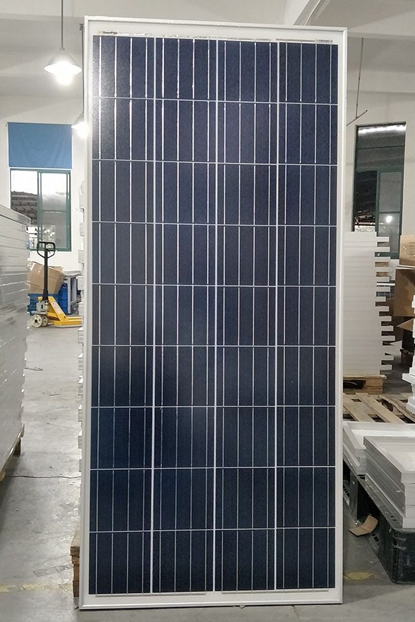
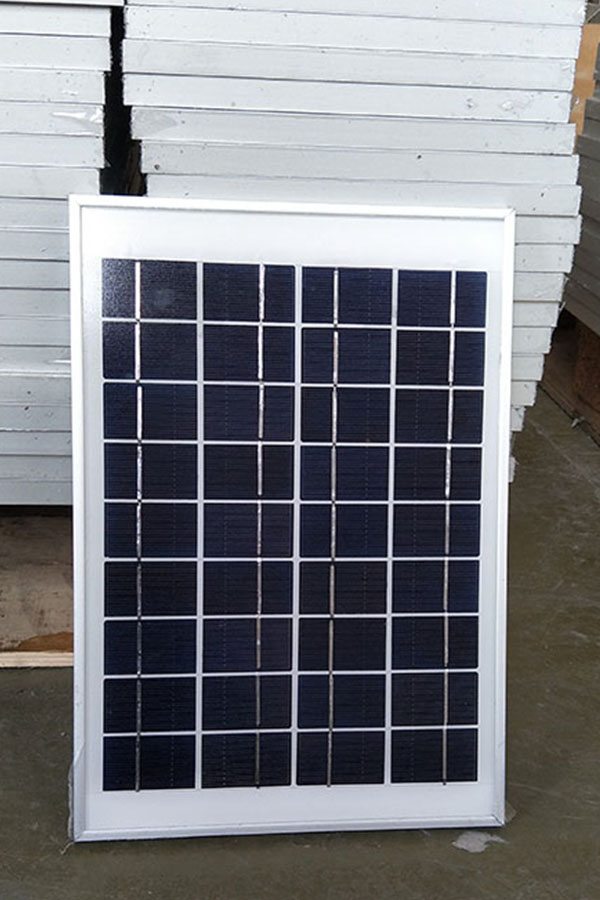
Poly-crystalline Solar Panel 5W
Technical parameter
Maximum Power(W) 5W
Optimum Power Voltage(Vmp) 9V
Optimum Operating Current(Imp) 0.56A
Open Circuit Voltage(Voc) 10.8V
Short Circuit Current(Isc) 0.62A
Mechanical Characteristics
Cell Type Polycrystalline
No of Cell 18 (3x6pcs)
Dimensions 175x270x18mm
Weight 0.65KGS
Front Glass 3.2mm,High Transmission, Low Iron,Tempered Glass
Temperature and Coefficients
Operating Temperature(°C): -40°C ~ + 85°C
Maximum System Voltage: 600V(UL)/1000V(IEC) DC
Maximum Rated Current Series: 10A
Temperature Coefficients of Pmax: -0.435%
Temperature Coefficients of Voc: -0.35%
Temperature Coefficients of Isc: 0.043%
Nominal Operationg Cell Temperature (NOCT): 47+/-2°C
Materials of solar panel
1).Solar Cell——Polycrystalline solar cell 156*156mm
2).Front Glass——-3.2mm, high transmission, low iron, tempered glass
3).EVA——-excellent anti-aging EVA
4).TPT——-TPT hot seal made of flame resistance
5).Frame——anodized aluminum profile
6).Junction Box——-IP65 rated, high quality, with diode protection
Superiority: high quality anodized aluminum frame, high efficiency long life, easy installation, strong wind resistance, strong hail resistance.
Features
1. High cell efficiency with quality silicon materials for long term output stability
2. Strictly quality control ensure the stability and reliability, totally 23 QC procedures
3. High transmittance low iron tempered glass with enhanced stiffness and impact resistance
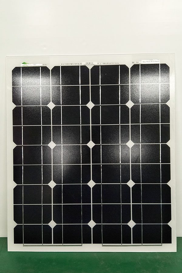
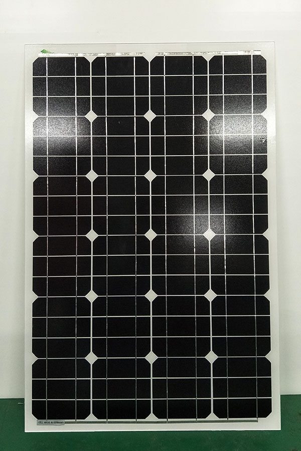
4. Both Poly-crystalline and Mono-crystalline
5. Excellent performance in harsh weather
6. Outstanding electrical performance under high temperature and low irradiance
Quality assurance testing
Thermal cycling test
Thermal shock test
Thermal/Freezing and high humidity cycling test
Electrical isolation test
Hail impact test
Mechanical, wind and twist loading test
Salt mist test
Light and water-exposure test
Moist carbon dioxide/sulphur dioxide
For Any Kind Of Help Contect Me On:
http://mrengineerpk.blogspot.com/
Facebook PAge:
https://web.facebook.com/MrEngineerpk/
Twitter:
https://twitter.com/Chaloay62
Instagram:
https://www.instagram.com/azeemmahmood62/?hl=en
Google Plus:
https://plus.google.com/u/1/115364231825793174477
This circuit was designed to be used with any FM Transmitter to greatly reduce or eliminate unwanted harmonics in your transmitted radio frequency. The schematic for 88-108mhz is shown in this video. For other custom frequency ranges, please refer to the online calculator link shown below. Failure to suppress these harmonics, can result in interference in other bands such as aircraft and military, and possibly result in the FCC knocking on your door. In the past I uploaded a video for a 4W and 1W FM transmitter. Both videos did not show a low pass filter in the schematic. To add one(highly suggested), you would simply add this circuit to the RF output of either one of those circuits. ALWAYS transmit on a frequency which is not in use!
Thanks For Watching!
**Help support this channel by sharing this video, as well as my other videos with your friends, and posting links to these videos on other websites and blogs**
Link to low pass filter schematic shown in this video:
http://www.iol.ie/~yellowbeard/NRG%20Kits/rf_low_pass_filter.htm
Link to a low pass filter calculator fro custom frequency ranges:
http://www.m0ukd.com/Calculators/Low_Pass_Filter_Calculator/
Link to online air coil inductor calculator:
http://www.circuits.dk/calculator_single_layer_aircore.htm
4W FM Transmitter video/schematic link(Easy/Very Good Transmitter!):
Very good 1W RF amp for boosting small transmitter output: